About this deal
I wanted to hide the USB serial and USB sound dongles in the box so I looked through my junk box for a USB Hub. I found a 4 port hub so I decided to add a USB memory key. But it doesn’t end here! That’s were the Power Cutter comes in. Thanks to Talpa PCB retrace of the BTE13-010 I was able to elaborate an evil power saving plan:
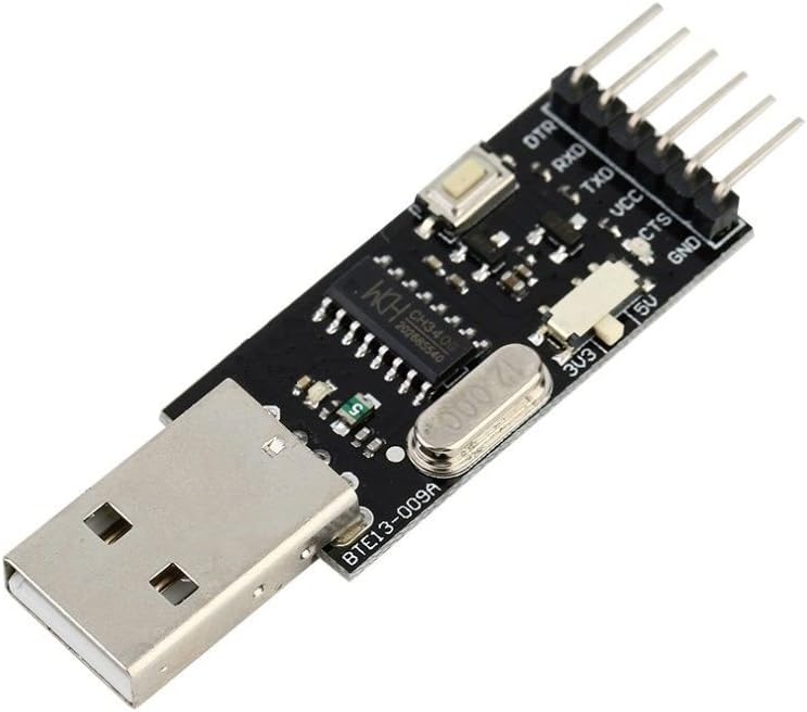
http://kiguino.moos.io/2014/12/31/how-to-use-arduino-nano-mini-pro-with-CH340G-on-mac-osx-yosemite.html Look at the Fritzing diagram above or follow the instructions below to connect the Arduino mini clone to the Serial to USB converter: BTE13-010--------------CH340G The first one I killed when I used a USB TTL adapter that I believe kept the TTL signal level at 5V even when selecting 3.3V. I now use TI TXU0202 in VSSOP-8 for this. Before, I used to use TI SN74LVC1T45's in SOT23-6, which can be easier to work with, as VSSOP-8 has 0.5mm pitch, whereas SOT23-6 has almost 1mm pitch, and can even be dead-bugged (soldered directly to thin wires in air). TXU0202 can handle either side with logic levels between 1.1V and 5.5V, which means it's pretty darn good for this. I also use the related TXU0304 in TSSOP-14 for SPI.soldering material and equipment (in this regard you can watch our tutorial Yet another tutorial on how to solder) I recently posted an instructable for an FLDigi compatible interface. It was largely based on a Hamcomm interface I designed as a hand out for a Ham / PC Usergroup talk I gave in 2005.
Be careful not to connect the TXD terminal of the BTE13-010 with the TXD terminal of the CH340G (or the two RDX terminals)! To find out why, read this clear guide from Sparkfun on serial port operation and connection. While Arduino is placed on the breadboard, only solder the four vertex joints. Why only four vertex? Because breadboard is made of plastic and if you accidentally hit it with your iron solder tip you’ll damage it.
Be the First to Share
I would stay with Laser GRBL open for testing until you can establish connections with it since to me it is easier to work in for diagnostics. Once LAser Grbl can comm with the laser and comp then you can swap over to LB. I have that model, too. That board is a mistake by design. It was very infuriating to find out the power supply was changing, while the levels on the data pins voltage were always 0..5V. Before starting, we specify that this tutorial can be used to learn how to install the drivers of the CH340G module (Serial – USB converter), on which the communication between the Arduino mini and the PC is based. keeping, as already mentioned, the Arduino inserted on the two connectors, solder the 4 pads in the corners. Why only these 4 points? Because the breadboard is made of plastic and excessive heat could damage it You want to use unidirectional voltage level translators or isolators for UART and SPI, and not bidirectional ones, as the latter tend to have glitches (in the low level signal part, when the direction sensing circuitry isn't sure of what is going on) in this kind of use that can cause transmission errors. So, I'd say forget TXB chips, and all bidirectional voltage level conversion chips.
 Great Deal